wm4000hba manual

Product Overview
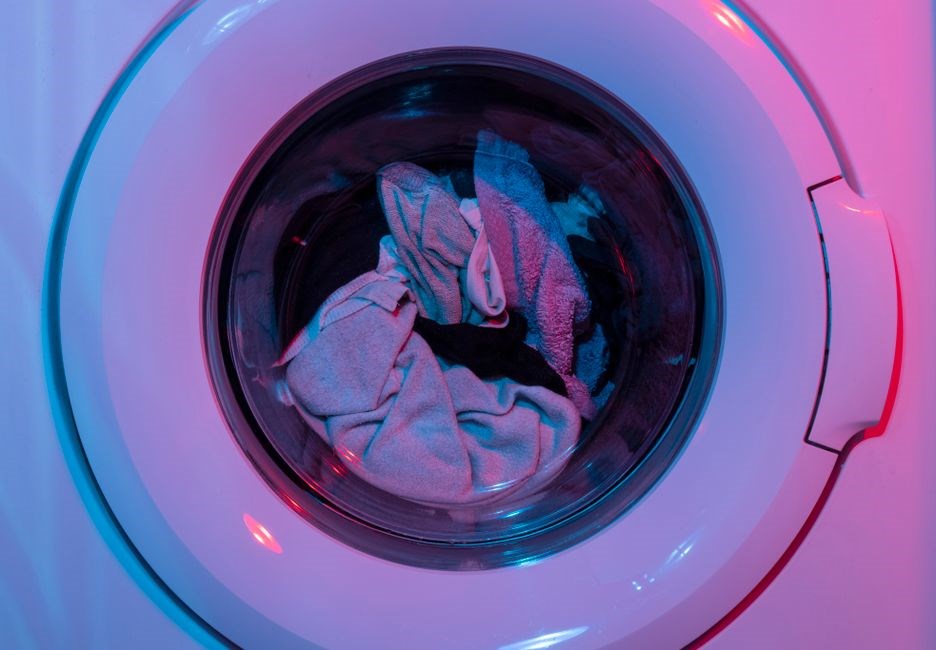
The LG WM4000HBA is a 27-inch‚ 4.5-cu‑ft smart front‑load washer featuring TurboWash360‚ SenseClean‚ SmartThinQ‚ and Energy‑Star efficiency. It offers steam cleaning‚ cold wash‚ and allergen‑reduction technology for deep‚ eco‑friendly performance. Ideal for families it cleans powerful while save water and energy!!!
Key Features
TurboWash360 delivers 30‑minute cycles‚ SenseClean auto‑detects load‚ SmartThinQ connects via app‚ SmartDiagnosis alerts issues‚ Sanitary & Allergiene cycles eliminate germs‚ ColdWash saves power‚ NSF Certified for safety‚ Energy‑Star rated for efficiency. Ideal for families.eco‑friendly!!!
TurboWash360 Technology
TurboWash360 is LG’s flagship rapid‑wash technology that cleans large loads in just 30 minutes.
The system uses five high‑pressure jets that spray water from multiple angles‚ ensuring every garment receives a thorough rinse.
A built‑in steam function lifts stains and eliminates allergens‚ while it adjusts water temperature and cycle length automatically.
The 4.5‑cubic‑foot drum accommodates bulky bedding and heavy fabrics without compromising efficiency.
Energy‑Star certification guarantees low power consumption‚ and the optional ColdWash setting saves even more electricity.
The washer’s quiet motor and vibration‑dampening design mean fast cycles don’t disturb the household.
With TurboWash360‚ users enjoy a deep clean‚ reduced drying time‚ and a fresher laundry room environment.
Perfect for busy families‚ the feature delivers convenience‚ performance‚ and sustainability in one sleek‚ front‑load machine.
The washer also offers a customizable cycle menu‚ allowing users to select from Quick Wash‚ Heavy Duty‚ or Eco Mode‚ each tailored to specific fabric types.
The front‑load design reduces wear on clothes‚ extending garment life.
LG’s advanced control panel displays real‑time cycle progress and estimated completion time‚ so users can plan their day.
Safety features include a child lock and automatic shut‑off if the door is opened mid‑cycle.
Fast‚ efficient!
Its quiet operation and low vibration make it ideal for homes with shared walls‚ ensuring a laundrydaily experience.
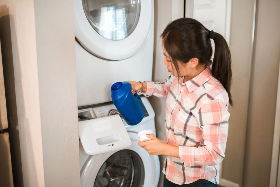
SenseClean Sensor
LG’s SenseClean sensor automatically detects the weight and soil level of each load‚ adjusting water usage and cycle time for optimal performance. The sensor’s micro‑processor calculates the exact amount of detergent and water needed‚ ensuring a thorough clean while conserving resources. It monitors temperature‚ fabric type‚ and load distribution‚ then selects the most efficient wash pattern. This intelligent system reduces energy consumption by up to 30% compared to standard cycles‚ and it shortens wash time without sacrificing cleanliness. The sensor also alerts users to any imbalance or excess moisture‚ prompting adjustments that prevent over‑washing or under‑washing. With SenseClean‚ users experience consistent results‚ extended fabric life‚ and lower utility bills. The feature is fully integrated into the SmartThinQ app‚ allowing remote monitoring and scheduling. It supports Eco‚ Normal‚ and Heavy cycles‚ automatically tailoring each to the load’s specific needs. The sensor’s precision helps remove allergens and bacteria‚ making it ideal for households with sensitive skin. LG’s commitment to sustainability is evident in this technology‚ which pairs advanced sensing with efficient motor design. The result is a cleaner‚ greener‚ and more convenient laundry experience.
LG’s SenseClean sensor calibrates load weight‚ using only the water and detergent needed. This saves energy‚ reduces fabric wear‚ and ensures a deep clean without residue. Real‑time adjustments keep cycles efficient‚ making the washer eco‑friendly and cost‑effective. Its sensor alerts users to imbalance‚ over‑washing daily.
SmartThinQ Connectivity
LG’s SmartThinQ connects the WM4000HBA to your home Wi‑Fi‚ enabling remote control via the LG SmartThinQ app. Users can start‚ pause‚ or cancel cycles from a smartphone‚ tablet‚ or PC‚ and receive real‑time status updates. The app displays water usage‚ cycle progress‚ and estimated completion time‚ helping you plan laundry around your schedule.
SmartThinQ also offers voice‑assistant integration‚ allowing hands‑free operation through Amazon Alexa or Google Assistant. You can ask the washer to begin a specific cycle‚ check the remaining time‚ or request a diagnostic report. The diagnostic feature sends error codes and maintenance alerts directly to the app‚ so you can schedule service or resolve issues without visiting a technician.
Firmware updates are delivered automatically over the air‚ ensuring the washer runs the latest software for improved performance and security. Energy‑monitoring tools track consumption‚ giving you insights into how different cycles affect your utility bill. With SmartThinQ‚ you can also set custom notifications for cycle completion‚ filter cleaning reminders‚ and low‑water alerts.
Additionally‚ the SmartThinQ platform supports multi‑device synchronization‚ so family members can share access and control the washer from any connected device. This convenience‚ combined with real‑time monitoring and proactive maintenance alerts‚ makes the WM4000HBA a truly connected appliance that adapts to your lifestyle.
Scheduling is flexible: set a start time for the next wash‚ and the washer will automatically begin when the network is available. If the Wi‑Fi connection drops‚ the machine pauses and resumes once connectivity is restored‚ ensuring no cycle interruption.
Data privacy is protected with end‑to‑end encryption‚ and users can opt out of data sharing. All communications between the washer and the SmartThinQ servers are secured‚ giving peace of mind while enjoying full connectivity.
Manual Contents
Installation‚ Operating Guidelines‚ Troubleshooting‚ Maintenance & Care‚ Warranty & Support. Step‑by‑step setup‚ cycle selection‚ safety tips‚ error codes‚ cleaning‚ filter replacement‚ energy tips‚ and warranty information for the LG WM4000HBA washer. Check the manual for details fast.!
Installation Instructions
Before installing the LG WM4000HBA‚ check the room for adequate space‚ level surface‚ and proper ventilation. Unpack the unit‚ remove packaging‚ and place it on a flat‚ stable floor. Align the door and ensure it opens freely. Connect the water supply hoses to the hot and cold taps‚ using the supplied fittings. Tighten the connections with a wrench‚ but avoid overtightening to prevent leaks. Attach the drain hose to the designated drain outlet‚ securing it with a clamp. Ensure the hose is not kinked or bent. Connect the power cord to the outlet‚ verifying the voltage matches the specification. Turn on the water supply and check for leaks at all connections. Test the washer by running a short cycle to confirm proper operation. If any leaks or errors occur‚ refer to the troubleshooting section. Keep the washer level by adjusting the feet; use a spirit level for precision. Ensure the door seal is clean and intact. Finally‚ allow the washer to settle for 30 minutes before use to ensure stability. Follow all safety precautions and local codes during installation. Additionally‚ position the drain hose at least 30 cm above the floor to prevent backflow. Ensure water inlet valves are fully closed before disconnecting hoses. Keep the area dry and free of debris to avoid contamination. Label hot and cold hoses for easy maintenance. Store the washer in a ventilated area when not in use. Follow local electrical codes for outlet placement. Use a surge protector to safeguard the appliance. Keep the washer in good condition clean. Keep it clean. and dry. now!
Operating Guidelines
Before starting a wash cycle‚ load the drum evenly‚ ensuring that heavy items are balanced with lighter ones. Do not overload; the 4.5‑cu‑ft capacity is designed for medium to large loads; Place delicate fabrics in the provided mesh bag and use the “Delicate” or “Wool” cycle for optimal care.
Select the desired wash program via the front panel or SmartThinQ app. The TurboWash360 feature delivers a 30‑minute cycle with five powerful jets‚ while the Steam option infuses hot steam for deep cleaning and allergen reduction. For eco‑friendly operation‚ choose the “Eco” or “Cold Wash” cycle to save water and energy.
After the cycle completes‚ open the door promptly to allow the drum to dry and prevent mildew. Use the “Rinse” or “Spin” options if you need a quick refresh. For maintenance‚ run a “Clean” cycle monthly to remove detergent residue. Always keep the door seal clean and dry‚ and check the filter regularly for lint buildup. If the machine displays an error code‚ refer to the troubleshooting section for resolution. Enjoy a spotless‚ fresh load every time!
To extend the life of your washer‚ avoid using harsh chemicals and always follow the detergent guidelines. For large items‚ pre‑treat stains with a gentle spot cleaner before loading. Keep the door latch and rubber gasket free of debris. Periodically inspect the water inlet hoses for kinks or leaks. If you notice any abnormal noise or vibration‚ stop the machine immediately and consult the manual for safety instructions.
Remember to unplug washer during maintenance.!!!
Troubleshooting Section
When the LG WM4000HBA does not perform as expected‚ consult the following diagnostic steps. 1. Power issues: Verify the outlet is functioning by plugging in another appliance. Check the circuit breaker and ensure the plug is fully seated. If the indicator light remains off‚ the internal power supply may be defective. 2. Door latch error: The washer will not start if the door is not securely closed. Inspect the latch for damage or debris and clean the gasket. 3. Water inlet problems: A clogged filter or kinked hose can prevent water from entering. Remove the filter‚ rinse‚ and straighten hoses. 4. Error codes: The display will show a two‑digit code. Refer to the manual for code meanings; common codes include 01 (door lock)‚ 02 (water inlet)‚ 05 (overheat). 5. Cycle not completing: If the cycle stops prematurely‚ check for a jam in the drum or a malfunctioning motor. Inspect the agitator and ensure no foreign objects are trapped. 6. Excessive vibration: This can result from uneven flooring or an unbalanced load. Level the machine with adjustable feet and redistribute the laundry. 7. Steam function failure: Verify the steam valve is not blocked. If steam is not produced‚ the heating element may need replacement. 8. Noise during spin: A worn bearing or loose part can cause loud noises. Inspect the drive belt and replace if necessary. 9. SmartThinQ connectivity: If the app cannot communicate‚ reset the Wi‑Fi module by unplugging for 30 seconds‚ then reconnect. 10. Firmware updates: Use the SmartThinQ app to download the latest firmware; an outdated version can cause performance glitches. If none of these steps resolve the issue‚ contact LG customer support or schedule a service appointment. Always unplug the unit before performing any inspection or repair. For detailed error code explanations‚ refer to the troubleshooting table in the user manual. The goal is to identify the root cause quickly and safely‚ ensuring the washer returns to optimal operation without compromising safety or warranty compliance. If the washer displays a flashing LED‚ consult the LED guide: a single flash indicates a door error‚ two flashes a water error‚ three flashes a motor error. For persistent issues‚ perform a factory reset by holding the start button for 5 seconds until the display clears. Additionally‚ ensure the drain hose is not kinked and is positioned above the floor to prevent backflow. Regularly clean the lint filter after each cycle; a clogged filter can cause overheating and cycle termination. Keep the detergent dispenser dry to avoid mold growth. Finally‚ verify that the machine is on a level surface; use a spirit level to adjust the feet. If the machine still fails to start‚ the control board may require professional service. Contact LG support for a diagnostic code and repair instructions.!!!
Maintenance & Care
Clean the drum weekly with a mild detergent. Empty the lint filter after each load. Inspect the drain hose for kinks. Keep the door seal dry to prevent mold. Check the water inlet filter monthly. Store the machine on a level surface to avoid vibration.!!! Maintain filter monthly. Check door seal regularly.!!!!!!!!!!
Cleaning the Drum
The LG WM4000HBA washer’s drum is designed for easy maintenance. To keep it clean‚ run a 30‑minute cycle with no clothes and a cup of white vinegar or a specialized drum cleaner. This removes detergent residue‚ mildew‚ and odors. After each wash‚ leave the door ajar for a few hours to allow air circulation and prevent mold growth. Periodically inspect the rubber door seal for cracks or debris; wipe it with a damp cloth and mild soap. The machine’s built‑in sanitizing cycle can be activated when you notice a musty smell; it uses high‑temperature steam to kill bacteria. Avoid harsh chemicals or abrasive scrubbers that can damage the drum’s finish. For heavy stains‚ apply a small amount of liquid detergent directly to the fabric before loading. Use the “Sanitary” or “Allergiene” settings for extra cleaning power. When the drum is dry‚ store the washer on a level surface to avoid vibration. Regular cleaning extends the life of the drum and ensures optimal performance. Follow the manufacturer’s guidelines for any cleaning products to avoid voiding the warranty. Additionally‚ use the built‑in sanitizing cycle once a month to keep the drum hygienic. Avoid using bleach unless the manual specifies it is safe for the drum material. Remember to keep the detergent drawer free from buildup to prevent clogs and ensure efficient washing!!!!!!
Filter Replacement
To replace the drain filter on the LG WM4000HBA‚ first ensure the washer is unplugged and the water supply is turned off. Locate the filter door on the front‑bottom of the unit; it is usually marked with a small icon. Gently pull the door outward‚ then rotate the filter counter‑clockwise until it loosens. Place a towel or shallow pan beneath the filter to catch any residual water. Remove the filter by pulling it straight out; you may need to use a flat‑head screwdriver to pry it slightly if it is stuck. Inspect the filter for lint‚ hair‚ or debris and rinse it under running water until clean. Re‑install the filter by inserting it back into the opening and turning it clockwise until it is snug but not overtightened. Close the filter door securely. Finally‚ plug the washer back in‚ restore the water supply‚ and run a short cycle to ensure proper drainage. Regular filter maintenance—every 1–2 months—prevents clogs‚ improves wash performance‚ and extends the life of the machine. If you notice a slow drain or a “water not draining” error‚ check the filter first; a clogged filter is a common culprit. For detailed illustrations‚ refer to the user manual’s filter section or the manufacturer’s support website. Remember to replace the filter if it shows signs of wear or damage‚ such as cracks or a warped shape‚ to maintain optimal functionality. Proper filter care is essential for efficient operation and helps avoid costly repairs or water damage to your home. Keep the filter area dry and free of excess moisture to prevent mold growth and maintain a hygienic washing environment. Follow these steps each time you service the filter to ensure the washer remains in peak condition and delivers clean‚ fresh laundry with every load.!!!!!!
When cleaning‚ avoid using harsh chemicals that could damage the filter material. If the filter is difficult to remove‚ gently tap the filter housing with a rubber mallet to loosen it. After reinstalling‚ check for any leaks around the filter seal by running a rinse cycle and inspecting the area. If leaks appear‚ tighten the filter slightly but do not overtighten‚ as this can damage the seal. Document the filter replacement date in a maintenance log for future reference. LG recommends using only the supplied filter; do not substitute with third‑party parts. The filter is designed to capture small particles that could otherwise clog the drain pump. By keeping it clean‚ you reduce the risk of pump failure and improve water efficiency. If you encounter a “Drain Error” code‚ reset the washer by turning it off for 30 seconds‚ then back on. This often clears minor drainage issues once the filter is cleaned. For any persistent problems‚ contact LG customer support or a certified technician. Proper filter replacement is a simple yet vital maintenance task that keeps your washer running smoothly and extends its lifespan. By following these steps diligently‚ you’ll enjoy reliable performance and cleaner laundry for years to come.!!!!!!
Additionally‚ inspect the filter housing for any visible damage or wear; replace the housing if cracked or warped to prevent water leakage. A well‑maintained filter system contributes to the overall energy efficiency of the washer‚ ensuring that each cycle uses the minimum required water and electricity. By following these steps diligently‚ you’ll enjoy reliable performance and cleaner laundry for years to come.!!!!!!
Warranty & Support
LG offers a 1‑year limited warranty covering parts and labor for the WM4000HBA. Service centers handle repairs; extended coverage can be purchased. Contact LG Support via phone‚ chat‚ or the official website for troubleshooting‚ parts‚ and repair scheduling. For details‚ visit LG.com!!
Warranty Coverage Details
LG’s warranty for the WM4000HBA provides a 1‑year limited coverage that protects against defects in materials and workmanship. The warranty includes parts and labor for any malfunction that occurs under normal use. If a component fails‚ LG will replace or repair the defective part at no cost to the customer. The coverage period begins on the date of purchase and is valid for 12 months. To file a claim‚ the owner must contact LG Customer Support via the official website‚ phone‚ or authorized service center. Proof of purchase‚ such as the original receipt or order confirmation‚ is required. The warranty does not cover damage caused by misuse‚ accidental drops‚ or improper installation. Additionally‚ any modifications or repairs performed by non‑authorized personnel void the warranty. The warranty also covers the motor‚ drum bearings‚ electronic control board‚ and water inlet valves. Shipping and handling for parts are included. The warranty is transferable to a new owner if the original owner provides a signed transfer form and proof of purchase. However‚ the warranty expires if the appliance is moved more than 10 feet from its original location without LG authorization. For extended protection‚ customers can purchase LG’s Extended Warranty Plan‚ which offers additional coverage for a longer period and includes roadside assistance for appliance issues. All warranty claims are subject to LG’s terms and conditions‚ and the company reserves the right to refuse service if the appliance does not meet the specified conditions. For more details‚ visit the LG support page for warranty claim instructions now.